About Us
BuildingSensors.com's SmartWand system is being developed by a design/builder passionate about learning how to build better buildings and an engineer passionate about developing appropriate technology to in support of the same. Together, they bring their respective skills to bear to achieve the shared goal of improving our built environment through research, observation, analysis, and response. The SmartWand system supports the principles of democratizing building science, raising our collective understanding of building performance, and engaging the broader community in a crowd-source approach towards building research.
Technical Overview
From a technical perspective, BuldingSensors.com's SmartWand is an apparatus that allows sensors to be embedded in a wall with a consistent geometry, capture sensor data values automatically over time, and deliver these data values to a central database in the cloud for analysis. Sensor data is captured from both in-wall sensors, and ambient sensors deployed both inside and outside (outside sensors include a weatherproof casing). All sensors are calibrated prior to shipment.
The standard SmartWand reference model has three basic elements:
-
wand - (1-3) sensors and microcontroller (uC) embedded in the wall system using an insulated carrier, or the uC can be tethered to support multiple wands per Figure 1 below
-
aggregator - small, low-power computer gathering wand data and communicating to cloud database via wired/wireless internet connection
-
cloud services (CS) - centralized, structured storage for implementation details (e.g. sites, wall planes, wands, aggregator) and sensor data, analysis tools, etc.
A simplified version has been implemented with a Wifi/internet enabled uC as depicted in Figure 1 which combines the wand and aggregator, resulting in two elements.
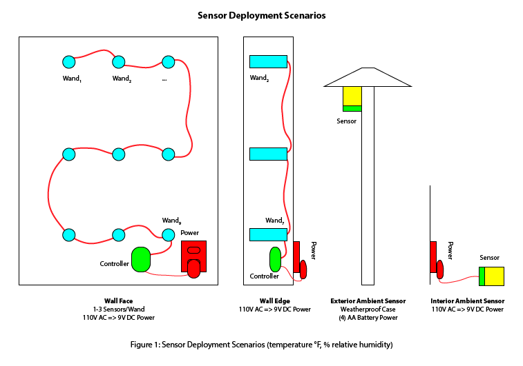
This SmartWand general reference model can be implemented using a variety of commercially off-the-shelf (COTS) or custom components depending on specific wall systems, research objectives, physical constraints, and cost considerations. In the initial release, the wand and aggregator elements have been combined into a single component through the use of a uC with build-in WIFI support allowing it to talk to the CS directly. The initial sensor design will support temperature and relative humidity (RH) measurements. Each sensor provides four data points to the uC: temperature, RH, timestamp (e.g. date and time), and the unique sensor ID. This platform provides the opportunity for additional data services (i.e. integration of other sensors for IAQ, etc). Power for wands and indoor ambient sensors is provided by 110v 15amp transformers or direct wired into existing AC power. Outside ambient sensors are either battery powered or hard-wired back to a uC associated with one of the wands.
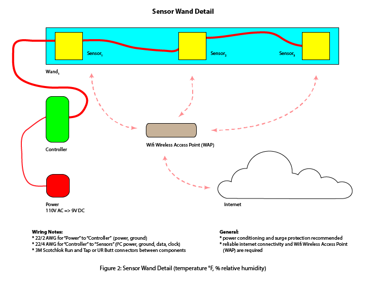
Wand detail, including wiring is depicted in Figure 2.
Installation
The SmartWand system is designed with a few basic criteria in mind: robust data capture and analysis, affordability, and ease of implementation to facilitate widespread adoption. To that last point, the installation of the system is designed to be as simple as possible while maintaining flexibility in design and customization when necessary for unique environments. The basic sensor carrier is designed to install easily into straw and cellulose wall assemblies prior to plastering by completing the following steps:
-
Locate and document local WIFI service. Details for configuring the SmartWand microcontroller are available here, and require an iOS or Android device. You will be required to enter your local WIFI details during this setup process.
-
Locate sensor positions and verify all parts have been assembled, including sensor carriers, wiring, power supply.
-
Install sensors in carrier into wall or ceiling system. For straw bale assemblies, pre-drilling with a ¾" - 1" ship's augur will greatly facilitate installation, particularly for edge-laid bales. A 1” ID thin-wall aluminum rod is first inserted into the wall. A dowel can be used to clear out any insulation out of the rod. Alternatively, a small tube can temporarily be taped to a vacuum to suck out remaining insulation. The sensors in carrier are then inserted into the rod. Finally, the rod is removed, while using a dowel to keep the carrier firmly in place.
-
Care should be taken to ensure wires are embedded at least 1.5" into the wall cavity; strike plates may be required over shallow installations across framing members. Surface-mounting with an appropriate wire guard is another convenient solution where applicable.
-
Install the indoor ambient sensor on a convenient location (e.g. tabletop, counter, floor, etc.). Sensor wands are "daisy chained" together on a shared 22/2 AWG power + ground wiring plan, and requires 9V DC power. Site wiring detail can either be hard-wired into a junction box, or can be plugged into a standard 120VAC outlet via transformer, or "wall cube". Always follow all applicable electrical codes and consult an electrician where required or desired. Surge protection is recommended. Power conditioning and backup should be considered for sites with variable or inconsistent power. Ensure that all system elements are subject to surge protection (e.g. SmartWand components, WIFI access point, internet gateway, etc.).
- Install outdoor ambient sensor module. Care should be taken to avoid positioning the module in direct sunlight, high wind/rain exposure, or standing/pooling water. The module should be positioned in such a location as to best capture ambient outdoor temperature/RH humidity levels while minimizing micro-climatic variations. Follow installation directions accompanying the module.